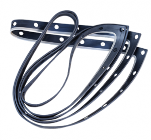
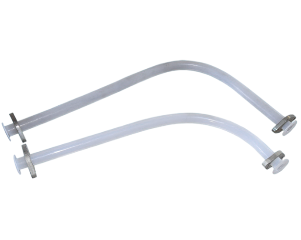
Ion-exchange membrane electrolyzer hose
Short Description:
In 2002, the company collaborated with Asahi Chemical Corporation of Japan to jointly develop high electrical density electrolytic cell rubber gaskets. In 2003, the company first provided 120000 tons of rubber gaskets for the Qilu project, which have advantages such as corrosion resistance, high elasticity, and high lifespan. The main products produced by the company include Asahi Chemical’s bipolar groove rubber gaskets, Western petroleum rubber gaskets, Denora rubber gaskets, FM-21 rubber gaskets, AZEC-F2 rubber gaskets, AZEC-B1 rubber gaskets, Uhde gaskets, Asahi Chemical’s electrolytic cell brackets and pins, various plastic products, and their products are exported to countries such as Indonesia, and are highly praised by customers at home and abroad.
Product Detail
Product Tags
Electrolysis Section: Electrolyzer hose
a. Anolyte System
The super purified brine from the super purified brine tank is fed through to each electrolyzer manifold and then distributed to each anode chamber where it decomposes into chlorine and sodium ions. A flow controller equipped with feed brine pipeline to each electrolyzer circuit monitors the super purified brine flow rate.
A two-phase stream of depleted brine and wet chlorine gas overflows from each anode chamber into a collection manifold equipped with each electrolyzer in which depleted brine and chlorine gas are separated.
The depleted brine from the manifold flows through branch pipe and main header into an anolyte tank by gravity, while the chlorine gas is sent to the B/L (chlorine gas processing section).
The depleted brine from the anolyte tank is pumped to the dechlorination section by level controller. Some of depleted brine in the anolyte tank is recycled to the electrolyzers by mixing with the fresh super purified brine.
Demineralized water supply line is provided for anolyte dilution to prevent salt crystallization during shutdown and for anolyte concentration adjustment to meet membrane requirement during start-up.
b. Catholyte System
Recycle caustic is fed to each electrolyzer manifold through a catholyte heat exchanger, and is then distributed to each cathode chamber where the cathode reaction decomposes water into the hydrogen and the hydroxide ions. A flow controller mounted at each electrolyzer circuit controls the recycle caustic flow rate.
A two-phase stream of caustic solution and hydrogen gas overflows from each cathode chamber into a collection manifold equipped with each electrolyzer in which the caustic solution and the hydrogen are separated.
The caustic solution from the manifold flows through the branch pipe, and the main header into catholyte tank by gravity, while the hydrogen gas is sent to hydrogen gas processing section through the branch and header pipe. Upon leaving the recycle caustic tank, the caustic solution separates into two streams: a product stream to the B/L and a recycle caustic stream to the electrolyzers.
The caustic soda heat exchanger heats or cools the recycled caustic to maintain the electrolyzer operating temperature at 85 ~ 90 deg-C. During start up, the caustic soda heat exchanger is used to warm the electrolyte in the electrolyzers, accelerating the full current load attainment without excessive voltage.
The electrolyzer caustic strength is monitored by a caustic density indicator, and normally kept at approximately 32wt%, the optimum membrane performance concentration, by controlling the demineralized water feed quantity into the recycled caustic stream.
To detect abnormalities of electrolyzers, electrolyzer voltage and temperature monitoring system are installed.
c. Gas system
The hydrogen gas pressure is controlled at approx. 400 mm H2O higher than chlorine gas pressure.